Modify Poses
The pose graph provides several nodes for modifying poses. Each of these nodes accepts an input pose and outputs the modified pose.
| Input | Type | Description |
|---|---|---|
Pose |
Pose | The pose to be modified. |
For the operation of a pose node, see pose graph node view.
Apply Transform
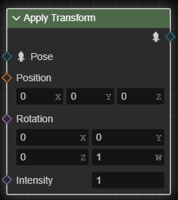
Apply transform node Applies a transform (translate and rotation) to the specified node of the input pose.
| Input | Type | Description |
|---|---|---|
Position |
3d-vector | The amount of modification to the position. |
Rotation |
Quaternion | The amount of modification to the rotation. |
Intensity |
Float | The intensity of application of the modification, in the range [0, 1]. 0 means that the modification is not applied at all, 1 means that the modification is applied completely. |
| Properties | Description |
|---|---|
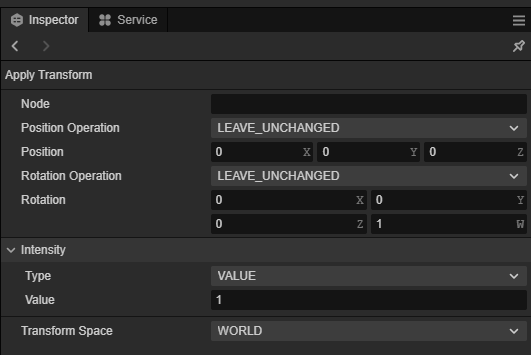
Node |
The name of the node to be modified. |
Position Operation |
Specifies how to modify the position. See Transform Operations |
Rotation Operation |
Specifies how to modify the rotation. See Transform Operation |
Transform Space |
Specifies the space in which the modification occurs; that is, the space in which the specified position input and rotation input reside. |
Transform Operation
The transform operation options specify how the applied transform node modifies the position or rotation. The options are listed below:
| Properties | Description |
|---|---|
| LEAVE_UNCHANGED | No modification. |
| REPLACE | When used as an application option for position, the position input is used directly as the new position of the node; when used as an application option for rotation, the rotation input is used directly as the new rotation of the node. |
| ADD | Adds the position input to the node's current position when used as an application option for position, or the rotation input to the node's current rotation when used as an application option for rotation. |
Copy Transform
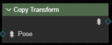
The Copy Transform node copies the transform of a node in the input pose to another node.
| Properties | Description |
|---|---|
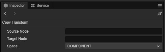
Source node |
The name of the node to be copied. |
Target Node |
The name of the node to copy to. |
Space |
Specifies the space where the copy occurs. When COMPONENT indicates that the copy occurs in component space; when LOCAL indicates that the copy occurs in local space. |
Set Auxiliary Curves
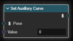
The Set Auxiliary Curve node modifies the current value of the specified auxiliary curve in the input pose.
| Input | Type | Description |
|---|---|---|
Value |
Float | The amount of modification to the auxiliary curve. |
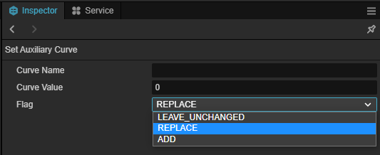
| Properties | Description |
|---|---|
Curve Name |
The name of the auxiliary curve to be modified. |
Flag |
Specifies how to modify the auxiliary curve. When LEAVE_UNCHANGED it is not modified; when REPLACE it means that the Curve Value input is used as the current value of the auxiliary curve; when ADD it means that the Curve Value input is added to the current value of the auxiliary curve. |
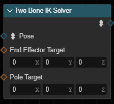
Double Skeleton IK
IK solving is often used to move or rotate a bone to a target position and drive the parent bone so that it remains the same distance from the parent (or within an acceptable range). For example, when moving a foot, the knee bone and thigh bone should bend accordingly.
Two-bone IK solver node solves IK problems consisting of two sections of (three bones) bones for the input pose. These three bones form a direct parent-child relationship, i.e. "child level - parent level - parent of parent level". The "child" is called the end-effector or end-bone, the "parent of parent" is called the root-bone (in this IK problem), and the "parent of parent " is called the intermediate bone.
Therefore, the "two" in "two-bone IK" should be interpreted as "two segments of bones" rather than "two bones".
When evaluating, the solver will transform the end and middle bones, and rotate the root bone so that the end bone reaches the specified position; and keep the distance between the parent and child levels unchanged, and the position of the root bone unchanged in the process.
For fixed end-bone and root-bone positions, an infinite number of solutions exist for the intermediate bones when solving. As shown in Fig:
The solver will try to find the "best" solution, but there may still be more than one such solution, and it may not be the desired one.
Therefore, in order to explicitly specify the orientation of the intermediate bones, the solver also allows to specify a pole-target to determine the bending direction of the skeletal chain.
| Input | Type | Description |
|---|---|---|
End-effector-target |
3d-vector | Target position of the end-effector. |
Polar target |
3d-vector | The position of the polar target. |
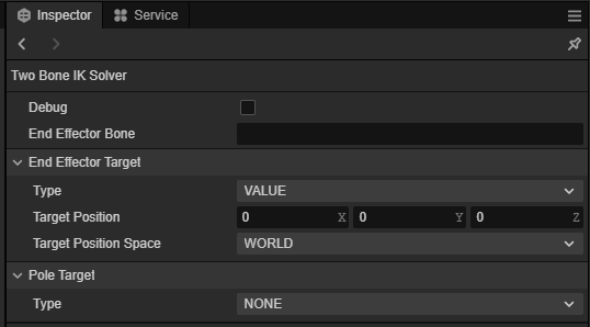
| Attributes | Description |
|---|---|
End-effector node |
The name of the end-effector node. |
End-Executor-Target |
The target setting of the end-effector. |
Polar target |
The polar target setting. |
Target settings
The target setting is used to describe the end-effector target or the poleward target. The options are as follows:
| Attributes | Description |
|---|---|
Type |
Target type. When VALUE, it means that the target position is represented as the specified (3D vector) value; when BONE, it means that the position of another bone is used as the target position; and when NONE, it means that the current position is used as the target position, i.e., the target is not solved for. |
Target Bone |
The name of the target bone when the target type is BONE. |
Target Position Space |
The space of the target position when the target type is VALUE. |