- 中文
- Cocos Creator
- Cocos2d-x
- AnySDK
-
Cocos Creator 1.9Version: 1.9
Build scene graph with scene editor
This section will introduce the workflow and tips of using Scene panel to create and editing scene contents.
Use Canvas as root node for all renderers
Newly created scene will have a Canvas node by default, it serves as the recommended root node for all renderer nodes. This has the below advantages:
Canvaswill fit the screen resolution automatically, use it as the root node will provide a solid screen size reference to all the renderer node in scene. Please read Auto fit for multi-resolution to learn details.Canvasdefault anchor point is at(0.5, 0.5)andCanvasnode will fit the screen size so any node underCanvaswill use the screen center as the origin. This will make scene and UI building easy (for example create a button with label at the center), it also makes positioning nodes with scripting much easier.
If you don't like using Canvas to make coordinate system's origin at the center of screen, you can also delete Canvas node and apply your own prefered policy.
Nodes contains only logical components
Besides renderer nodes (nodes with renderer components attached, such as Sprite, Label, EditBox, etc), we also needs nodes to contain components that control the main loop or specific gameplay logical script. It's recommended to put these nodes at the root of the scene, to be a sibling of Canvas node:
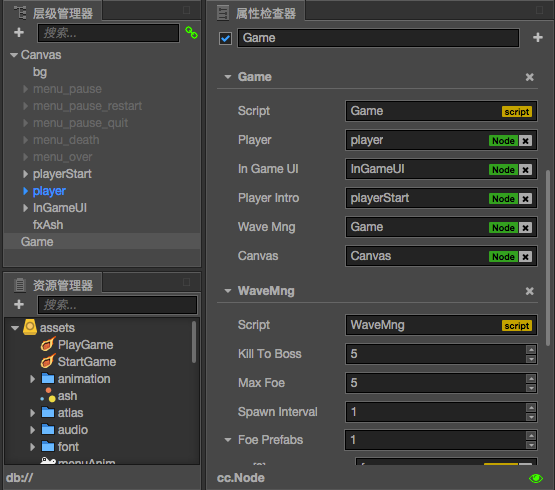
You can see besides visual nodes such as background, menu and character, we have a Game node that contains all main loop and main function module that sits with Canvas node. This way any collaborator can easily find the main logic components and referenced nodes.
Create node with preset
To quickly populate your scene with all kinds of renderer and UI nodes we can start with Create button (the plus icon) on the left top of Node Tree panel. The pop up menu is identical to main menu's Node Presets, you can create a node with useful component already setup in your scene.
You can select a node in Node Tree to be the parent node before you create new node.
Empty node
In the Node Presets menu, you can choose Create Empty Node to make a node without component. An empty node can be used as container for other nodes, or it allow you to add component that you need, all from scratch.
Renderer node
The next category of Node Presets menu is Create Renderer Nodes, we can find node preset already has Sprite, Label, ParticleSystem or TiledMap attached with placeholder assets that can give you a quick start.
These nodes with renderer components cannot be replaced by other component combination or user script, so they are categorized as Renderers. Each node can only attach one renderer component. If you need to combine different renderer components you should have multiple nodes to hold them.
UI node
There's also a Create UI Nodes category in Node Presets menu. You can create UI elements such as Button, Widget, Layout, ScrollView and EditBox.
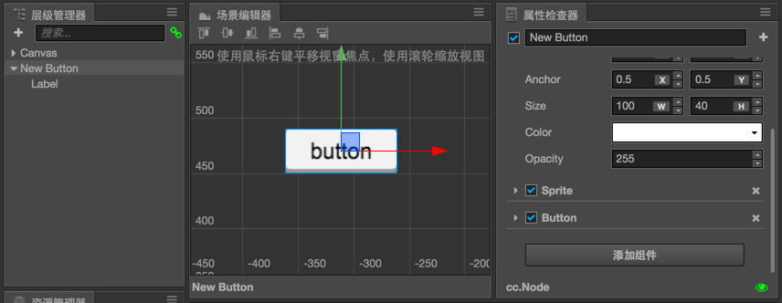
Most of UI nodes contains at least one renderer component. Take Button node as example, it contains a node with Button and Sprite to serve as background, and a node with Label for text displaying.
Use Node Presets to quickly create node with basic functions is recommended for general scene creating purpose, we can also add or customize components on those node presets to exactly fit our need.
Tips on efficient scene editing
- Select a node in Node Tree panel, and press Cmd/Ctrl + F to focus on this node in Scene panel.
- Select a node and press Cmd/Ctrl + D to duplicate the node in the same location.
- To multi-select nodes in Scene panel, you can hold Cmd/Ctrl button and click nodes one by one. Same operation applies in Node Tree as well.
- Hover your mouse on a node in Scene panel will show the node's name and bounding box, click your mouse will select the current displaying node. This way of selecting node in complex scene structure can be more successful.
Align nodes
The top bar of Scene panel has a series of button can be used to align multiple nodes.
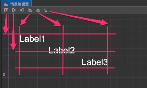
If we have selected 3 Label nodes, the align buttons from left to right will have following effect:
- Align nodes using the top most bounding box edge.
- Align nodes using the average vertical center line.
- Align nodes using the bottom most bounding box edge.
- Align nodes using the left most bounding box edge.
- Align nodes using the average horizontal center line.
- Align nodes using the right most bounding box edge.
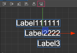
Be aware that align node function use each node's bounding box for reference, not their position. Below we align 3 Label nodes with different width to the right, and their x position are not considered.