Cocos Creator
Rendering Debug View
Note: The built-in rendering debugging feature is only available for materials using the Surface Shader framework**.
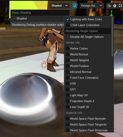
By selecting the corresponding debug mode in the upper-right corner of the scene preview window in the editor, you can view the model, materials, lighting and other computational data on the same screen, and quickly locate the problem when the rendering effect is abnormal.
To facilitate pixel-by-pixel comparison, we use full-screen debugging instead of picture-in-picture display, which allows us to quickly switch between different data in the same screen to locate rendering errors, and to use the color picker to explore the pixel-specific values.
In addition, Surface Shader has a built-in Irrational Number Visualization feature, so once some pixels appear to have abnormal and alternately blink, then the rendering calculation of these pixels appears irrational, please use the single debug mode to check the model tangent or other related data.
The rendering debugging functions are subdivided into the following three categories.
1. Common Options
Debugging options that are in effect in either single or combined mode, including:
| Name | Function | Debugging Tips |
|---|---|---|
| Lighting with Base Color | Check to show normal material illumination, check off to show the effect of white mold pure illumination. | You can see the effect of AO, GI and other indirect light related effects more obviously. |
| CSM Layer Coloration | Cascading shadows are stained layer by layer from near to far, distributed as reddish, greenish, bluish, and yellowish, with no staining in areas beyond the shadows. | Allows you to view and confirm the fineness of the scene shadows. If three or four layers accounted for too little shading is too fine, should increase the shading visible distance. If the ratio of one or two layers is too small, it means that the shadows are too coarse and the visible distance of shadows should be reduced. |
2. Single mode
The debugging focus , and the entire scenario visualizes this data output.
The debuggable data includes four major categories.
I. Primitive Model Info
| Name | Function | Description and debugging tips | Dependencies |
|---|---|---|---|
| Vertex Colors | Vertex Colors | Must check USE VERTEX COLOR in material | |
| World Normal | World Normal | ||
| World Tangent | World Tangent | If there are irrational numbers or unusual lighting effects in the calculation you can focus on checking here, if it is black then the model tangent is not turned on but normal mapping or anisotropy is turned on. | Exclusion cannot be selected in the model's tangent settings Must have USE NORMAL MAP or IS ANISOTROPY checked in the material |
| World Position | Visualize vertex coordinates (no scaling) | RGB channels display the XYZ axis coordinate data. You can judge the difference of world space axis by color, and the model size by light and dark. | |
| Mirrored Normal | Show normal map flip reuse markers | To improve normal map utilization, some symmetric models (e.g., faces) will only bake half of the normals and reuse the data in the normal map using mirror markers for the other half. If the value of this marker does not change at all on the model, it may cause the normals of the other half of the model to show unusual effects such as bump flip. | Must check USE NORMAL MAP in the material |
| Front Face Coloration | Display front or back faces | With the default single-sided model, the normals are not automatically distinguished and the light and dark seen on the front and back sides of the model are the same. When a single-sided model uses a double-sided material, it automatically distinguishes between the front and back normals, and the light and dark seen on the front and back sides of the model are different. The mark is white for the front side of the model and black for the reverse side. It can be used to check the light and darkness of the single-sided model. | |
| UV0 | Display the First UV | ||
| UV1 | Display the second UV | Must be checked in the material HAS SECOND UV | |
| Lighting MAP UV | Display the lighting mAP UV | If the light mapping effect is not correct, you can turn on this option and compare the general area of the light mapping to check the error. | Must bake scenes |
| Projection Depth Z | Display (0-1 non-linear variation) depth | Too far away of the far clip plane will result in a large depth value in the near field. | |
| Linear Depth W | Display (0-1 linear variation) depth | Too far away of the far clip plane will result in a large depth value in the near field |
II. Primary Material Info
| Name | Function | Description and debugging tips | Dependencies |
|---|---|---|---|
| World Space Pixel Normals | You can compare with the corresponding vertex data to see if the effect of normal mapping is correct | ||
| World Space Pixel Tangent/Binormals | Can compare with corresponding vertex data to see if normal mapping affects it correctly | Cannot be selected for exclusion in the model's tangent settings Must have USE NORMAL MAP or IS ANISOTROPY checked in the material | |
| Base Color | |||
| Diffuse Color | Base colors affecting diffuse illumination calculated from natural colors and other material data | ||
| Specular Color | The base color affecting specular reflective lighting calculated from intrinsic color and other material data | ||
| Opacity | Smaller means more transparent | Must have Alpha Blend enabled in the material | |
| Metallic | |||
| Roughness | |||
| Specular Intensity | Display the multiplication of non-metallic reference mirror reflectance F0 | If the specular is black, please check if this field is set to 0. |
III. Lighting Info
| Name | Function | Description and debugging tips | Dependencies |
|---|---|---|---|
| Direct Diffuse | |||
| Direct Specular | |||
| Direct Lighting | Direct Diffuse + Direct Specular | ||
| Ambient Diffuse | |||
| Ambient Specular | |||
| Ambient Lighting | Ambient Diffuse + Ambient Specular | ||
| Emissive | Display the emissive in the material | ||
| Light Map | Display baked lightmap RGB colors | Must bake scenes | |
| Shadows | Show shadows of directional light, spot light, point light | Shadows must be enabled in the scene's Inspector panel and light sources, and objects enabled to receive shadows | |
| Ambient Occlusion | Show the color of AO map in the material and real-time AO |
IV. Misc Info
| Name | Function | Description and debugging tips | Dependencies |
|---|---|---|---|
| Fog | Display the fog effect factor, the larger it is, the denser the fog is | Fog effect must be enabled in the scene's Inspector panel |
3. Render Composite Options
The debugging focus , and each module can be blocked or turned on, with modules unrelated to each other, to see how different modules affect each other's rendering effects.
Single mode has higher priority than the composite mode,
Including:
| Name | Function | Description and debugging tips | Category |
|---|---|---|---|
| Direct Diffuse | Enable/Disable Direct Light Diffuse | Affect Directional, Spot, and Point Light | Lighting |
| Direct Specular | Enable/Disable Direct Light Specular Reflection | Affect Directional, Spot, and Point Light | Lighting |
| Ambient Diffuse | Enable/Disable Ambient Light Diffuse | Influence Skylight | Lighting |
| Ambient Specular | Enable/Disable Ambient Light Specular Reflection | Influence Skylight | Lighting |
| Emissive | Enable/Disable Emissive | If some objects are too bright or exposed, try to turn off this option is not set in the material unnecessary self-illumination | Lighting |
| Light Map | Enable/Disable Baking Light | Affect Baking | Light |
| Shadows | Enable/Disable Direct Light Shadows | Affect Live Directional Light / Spot Light / Spot Light Shadows and Baked Directional Light Shadows | Lighting |
| Ambient Occlusion | Enable/Disable Ambient Occlusion | Influence Skylight | Light |
| Normal Map | Enable/Disable Normal Map | If the lighting is unusually scattered, try turning this option off to see if the normal map is scrambling at the wrong intensity. If the lighting effect is wrong or appears irrational, try turning this option off to see if the model is not tangential | Materials |
| Fog | Enable/Disable fog effect | If the scene color is abnormally gray, try turning off this option to see if the fog parameter is not set properly | Environment |
| Tone Mapping | Enable/Disable Tone Mapping | If the scene color is too different from the original material, try to turn off this option to see if it is normal, indicating that UseHDR should not be checked in the scene panel | Color Space |
| Gamma Correction | Enable/Disable Gamma Correction | If the scene is unusually colorful and dark, try turning off this option to see if it is normal, indicating that the mapping resources may have been gamma corrected multiple times | Color Space |
4. Advanced Usage
- Manual inserting vertex shader outputs and fragment shader inputs: with the new varying property introduced in the Surface Shader framework, vertex shader outputs and fragment shader inputs can be accessed in particular Surface Functions.
- Surface Shader and legacy shader codes can be used in the same render loop as long as the varying vertex data are kept consistent between the two.
Public function libraries
The library headers can be found under assets -> internal -> chunks -> common folder in different categories.
The functions in the library do not depend on any internal data (engine related uniform, mapping, etc.) and can be used directly as tool functions.
Surface already automatically contains common public function headers internally, which can be classified according to type as:
| Folder Name | Function Usage |
|---|---|
| color | color-related functions (color space, tonemapping, etc.) |
| data | Data-related functions (compression and decompression, etc.) |
| debug | Debug View-related functions |
| effect | Scene effect-related functions (water, fog, etc.) |
| lighting | lighting-related features (brdf, bsdf, attenuation, baking, etc.) |
| math | math library (coordinate transformation, numerical determination and operation, etc.) |
| mesh | model-related functions (material conversion, model animation, etc.) |
| shadow | shadow-related functions (pcf, hcs, etc.) |
| texture | mapping-related functions (sampling, mip calculation, etc.) |